Goal:

Replace drone propellors with compressed gas actuation for flight in low gravity, no atmosphere environments.
Method:
1. Physical proof of pneumatic actuation comparable to a propellor-based drone’s maneuvers
- Translational Testbed
- Attitude Testbed
2. Digital twins of testbeds
- Translational simulations
- Attitude simulations
- Validation of simulations
3. Control laws for On/Off Actuation
- Hysteresis Controller
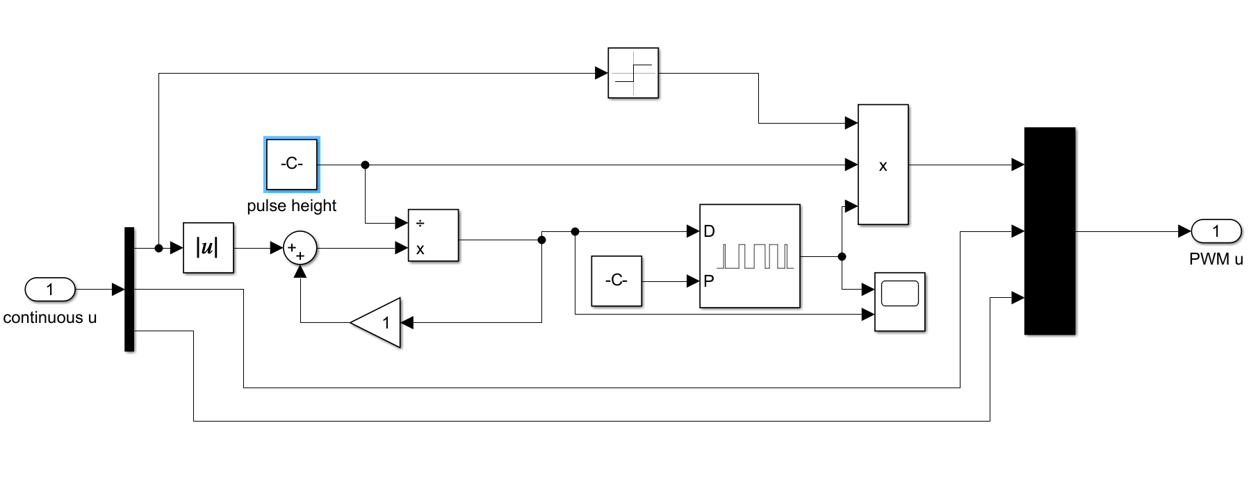
- PID-PWM Controller
- Optimal Bang-Bang Controller
Contribution
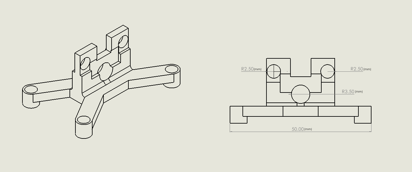
Once I defined both systems’ requirements, I used common electronics, pneumatic tubing/connectors, and 80/20 for the initial development. Using CAD and a 3D printer, I designed the components specific to this project. I then implemented, tested, and validated both test beds.
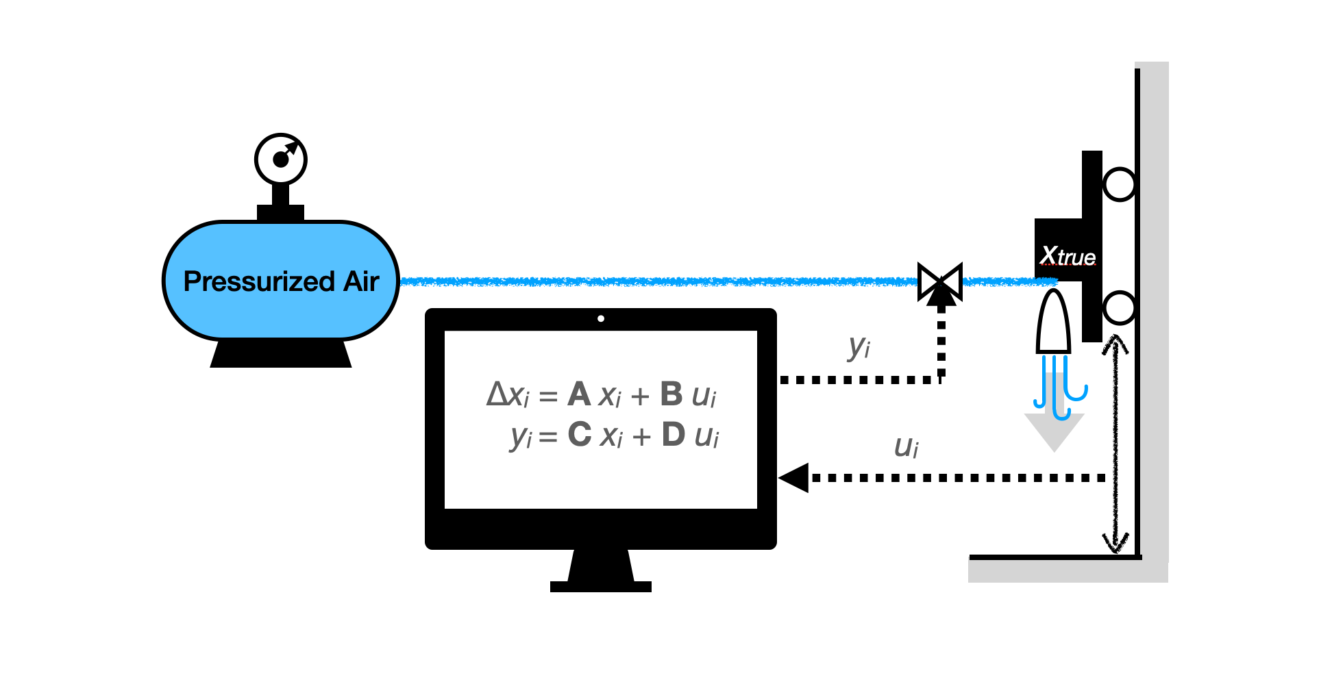
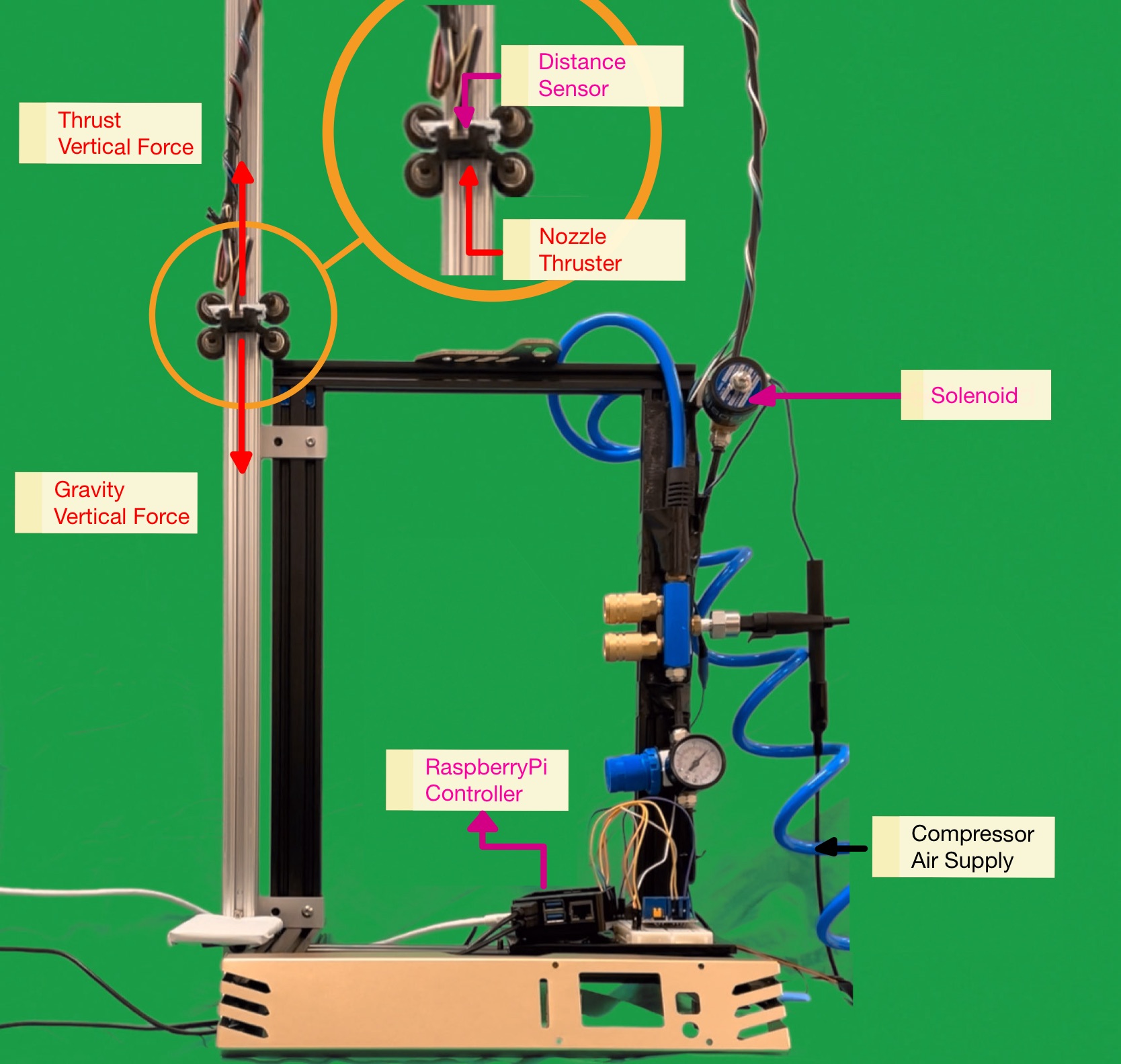
Translational Test Bed
- The pneumatically powered vehicle can only move in one dimension.
- The vehicle can be actuated using compressed air from a separate compressor.
- The vehicle has limited impedance from the device that holds it to one dimension. This includes limiting friction, outside forces of any tubes or wires connected to the vehicle, and reaction forces applied to the vehicle.
- The test bed must be able to estimate the vehicle’s state using appropriate sensors.
The one-degree-of-freedom test bed demonstrates vertical translation control using pneumatic actuation.
Rotational Test Bed
- The vehicle is only allowed to rotate with no translation.
- Free rotation is allowed in all directions where rotation in one direction does not limit rotation in another.
- The ability to mount various devices for testing a vehicle’s attitude adjustment abilities.
- A system with limited resistance to rotation of the system including minimal friction while rotating and little to no effect of outside forces on the vehicle’s rotation.
- The ability to estimate the states of the system with onboard sensors.
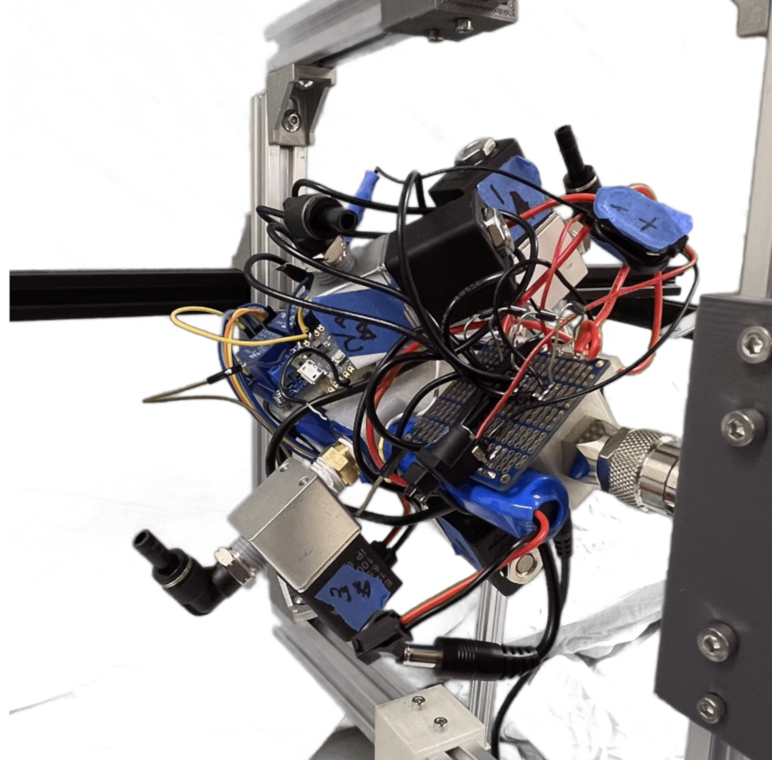
The attitude test bed’s purpose is to allow tests of rotation from a pneumatically actuated vehicle at all angles.
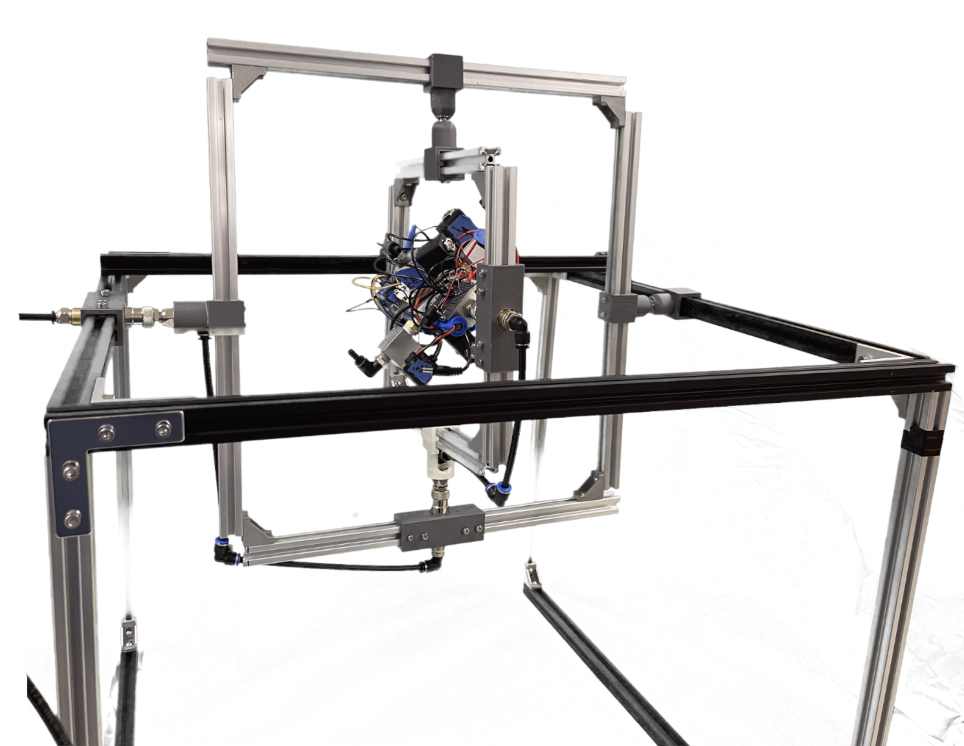
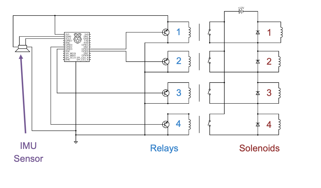
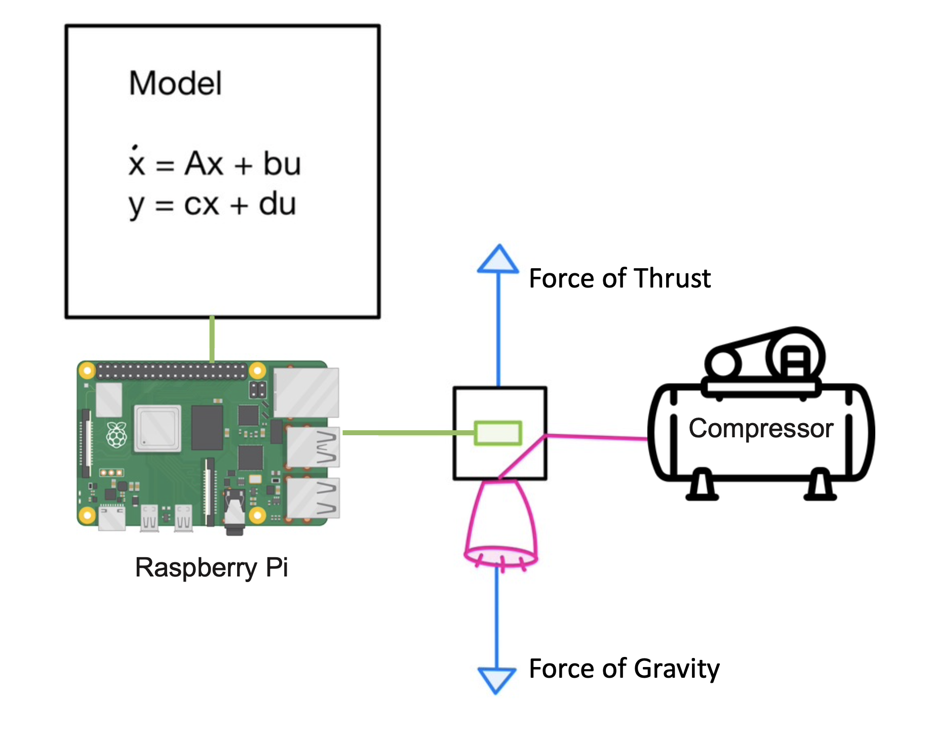
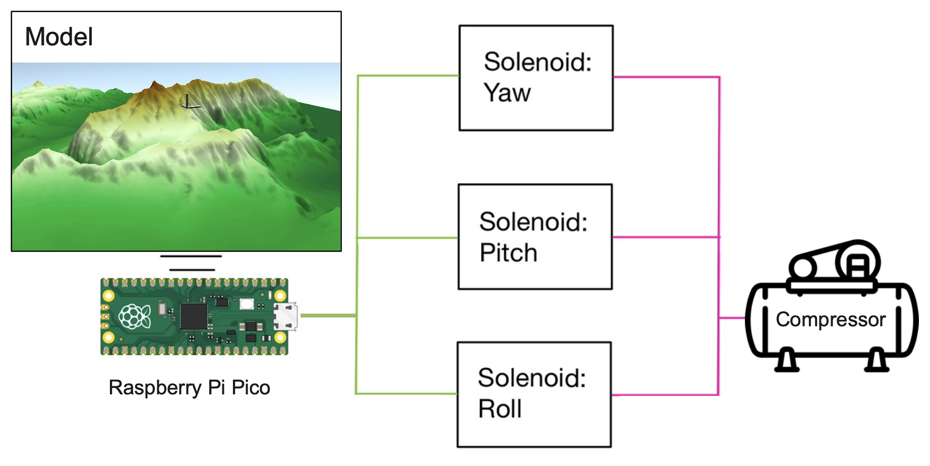
Each solenoid releases compressed gas in a different direction inducing rotation within the gimbal test bed. The body rates of the system are picked up by the IMU sensor onboard which are integrated and used to inform the controller of when to turn on or off the compressed gas.
The vehicle at the center of the gimbal controls the release of compressed gas using solenoids, a relay, IMU Sensors, batteries, and a Raspberry Pi Pico.
Simulation
GitHub files containing simulations and Python testbed scripts are found here.
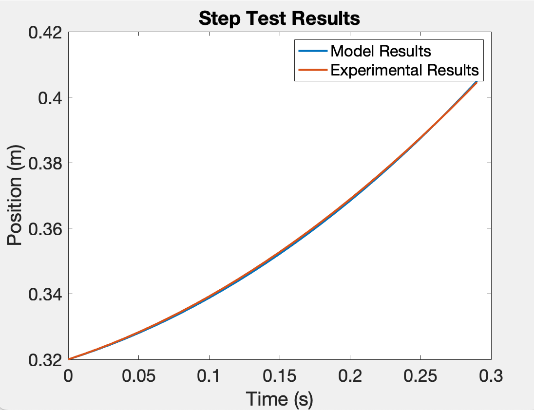
For the translational simulation, MATLAB rigid body numerical integration using state space and a force balance allowed a simple representation of a mass translating in 1DoF. Validation of The Hopper was done by comparing the simulation developed in MATLAB against the estimated states from the test bed. The values for the spring constant and friction were empirically tuned in the model to match the sensor readings from the test bed based on the results of a drop test and a step test.
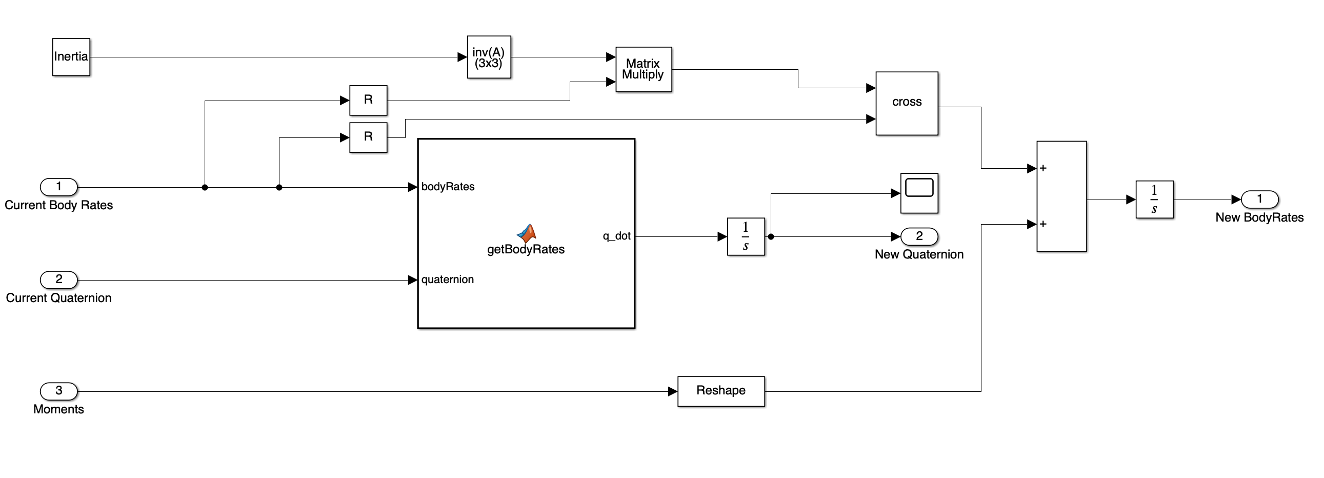
To describe rotation, I used Simulink rigid body dynamics with quaternions to describe the attitude and the half-angle formula to calculate the new body angles of the system.
Control Theory
Below are a few results from the control laws I developed. Please view my thesis paper for a full derivation of all three control laws.
Translational Controller Simulation Results
Plotted below is a comparison of all controllers for the hopper from the simulation.

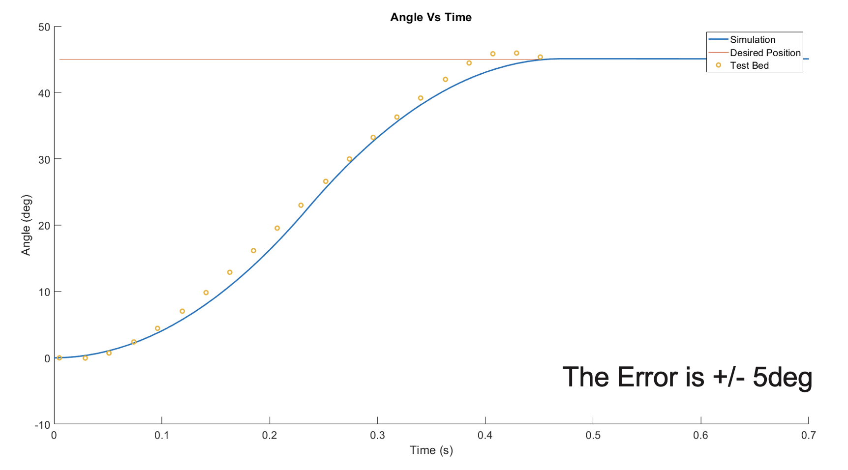
Optimal Controller for Attitude Control:
In the following chart, the optimal rotational controller was tested in the simulation and the test bed. The result is almost identical with an error of pm 5 degrees.